What is Operational Amplifier ?
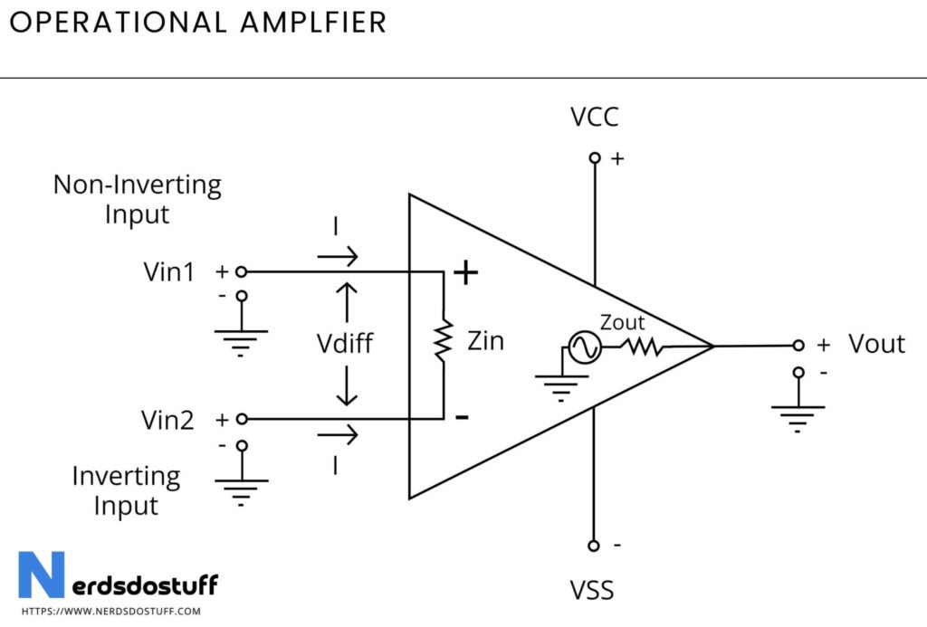
An operational amplifier, known as an op-amp, is a an important component in electronic circuits, particularly in analog applications. It’s a high-gain amplifier with two inputs, one inverting and the other non-inverting, and a single output. Inside, it consists of multiple transistors and resistors configured to amplify small input signals accurately. Op-amps have very high input impedance and low output impedance, enabling them to amplify signals precisely. With their large open-loop gain and high common-mode rejection ratio, op-amps excel in applications requiring accurate amplification and signal conditioning.
Op-amps are used for voltage amplification, signal filtering, and performing mathematical operations like addition, subtraction, integration, and differentiation. Also, they serve in oscillator circuits, comparators, and voltage regulators. Configurable into different circuit arrangements such as inverting amplifiers, non-inverting amplifiers, differential amplifiers, and active filters, op-amps are fundamental in audio amplifiers, instrumentation amplifiers, feedback control systems, and other electronic systems requiring precise signal processing.
Operational Amplifier Circuit
Working of Operational Amplifier
An operational amplifier, or op-amp, functions by comparing the voltages at its input terminals, amplifying the difference between them by a large factor (known as the gain), and then producing an output voltage that reflects this amplified difference. Regardless of the exact voltage levels, the op-amp focuses on the disparity between the inputs, magnifying even tiny differences significantly. This amplified output voltage swings high or low depending on the inputs and the gain setting, making op-amps invaluable for various applications in electronics where precise signal manipulation and amplification are required.
Types of Operational Amplifier
There are two main types:
- Inverting Operational Amplifier
- Non-Inverting Operational Amplifier
1. Inverting Operational Amplifier
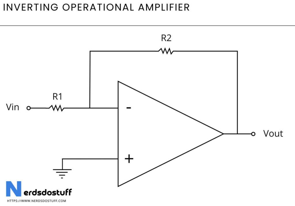
An inverting operational amplifier (op-amp) configuration utilizes the inverting input terminal (-) as the primary input and the non-inverting input terminal (+) as a reference. The input signal is applied to the inverting terminal through a resistor, while the feedback network is connected between the output and the inverting input. The output voltage of the op-amp is inverted with respect to the input voltage due to the configuration, resulting in a phase shift of 180 degrees. This setup provides a high level of control over the amplification factor and allows for the implementation of various signal processing functions, such as voltage amplification, filtering, and mathematical operations.
2. Non-Inverting Operational Amplifier
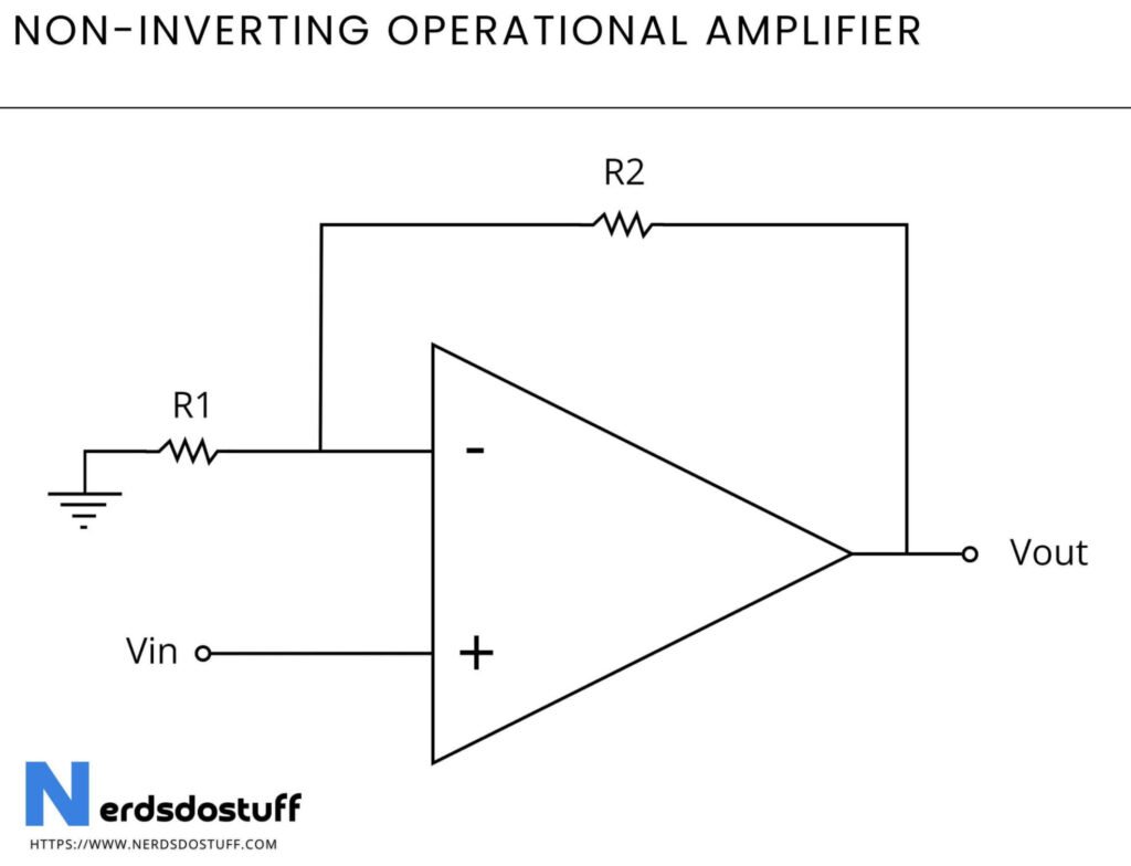
A non-inverting operational amplifier (op-amp) configuration utilizes the non-inverting input terminal (+) as the primary input and the inverting input terminal (-) as a reference. The input signal is directly applied to the non-inverting terminal, while the feedback network is connected between the output and the inverting input. Unlike the inverting configuration, the output voltage of the op-amp in the non-inverting setup retains the same phase as the input voltage. This configuration provides a means to amplify signals while maintaining the same polarity, offering advantages such as high input impedance and improved stability compared to the inverting configuration. It is commonly employed in applications where signal fidelity and minimal distortion are crucial, such as audio amplification and precision instrumentation.
Characteristics of Operational Amplifier
| Characteristic | Description |
|---|---|
| Input Impedance | High input impedance, typically in the range of megaohms, minimizes loading effects on input sources |
| Gain | Extremely high voltage gain, often exceeding 100,000, amplifies input voltage differences greatly |
| Bandwidth | Frequency range over which the op-amp can operate effectively, typically ranging from kHz to GHz |
| Slew Rate | Rate at which the output voltage can change per unit of time, expressed in volts per microsecond |
| Common-Mode Rejection | Ability to reject interference or noise common to both input terminals, expressed in decibels (dB) |
| Output Voltage Range | Maximum and minimum voltage levels the op-amp can output without distortion or saturation |
| Supply Voltage Range | Range of voltage levels required to power the op-amp, typically specified as a minimum and maximum |
| Input Offset Voltage | Small voltage difference between the input terminals required to nullify the output voltage |
| Input Bias Current | Small current flowing into or out of the input terminals, influencing the input voltage levels |
| Temperature Range | Operating temperature range within which the op-amp functions reliably |
Applications of Operational Amplifier
- Signal amplification
- Filters (low-pass, high-pass, band-pass)
- Instrumentation amplifiers
- Comparators
- Voltage followers
- Adders and subtractors
- Integrators and differentiators
- Oscillators
- Voltage regulators
- Current sensing and measurement