What is Comparator ?
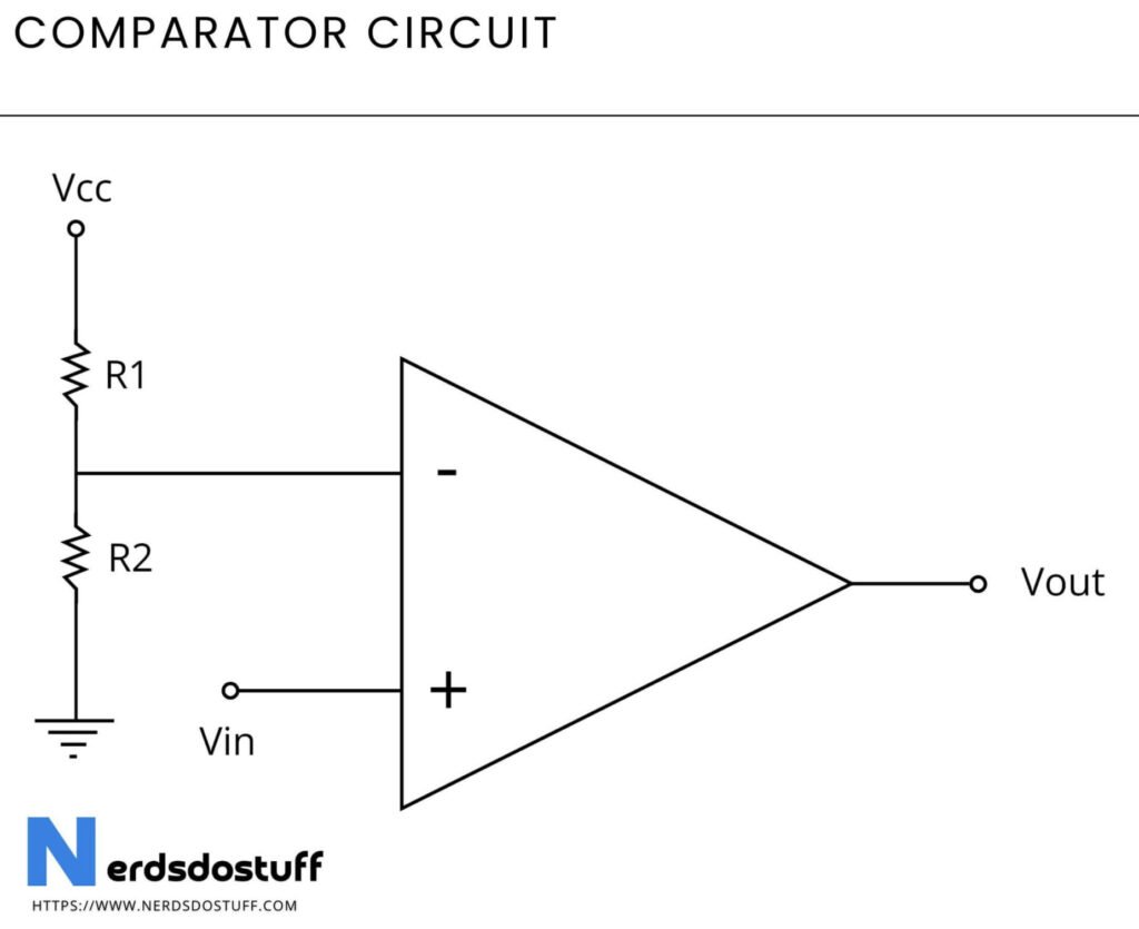
A comparator is an electronic circuit or device that compares two voltages or signals and outputs a digital signal indicating which one is larger. It typically consists of an operational amplifier (op-amp) configured with positive and negative input terminals, with one input connected to the voltage or signal to be compared and the other connected to a reference voltage or signal. When the voltage at the non-inverting input is greater than that at the inverting input, the output of the comparator goes high (logic level “1”). Conversely, when the voltage at the inverting input is greater, the output goes low (logic level “0”). Comparators are used in applications such as voltage level detection, zero crossing detection, waveform shaping, and digital signal processing. They provide fast response times and high accuracy in determining the relative magnitudes of input signals.
Comparator Circuit

Working of Comparator
A comparator works by continuously comparing two input voltages and producing a digital output signal based on their relative magnitudes. It typically consists of an operational amplifier (op-amp) with a positive (+) and a negative (-) input terminal, along with a reference voltage. When the voltage at the non-inverting input (+) is higher than that at the inverting input (-), the op-amp’s output swings to its maximum positive voltage, representing a logical high (usually denoted as “1”). Conversely, when the voltage at the inverting input (-) exceeds that at the non-inverting input (+), the output swings to its maximum negative voltage, representing a logical low (usually denoted as “0”). This behavior creates a binary comparison between the two input voltages, indicating which one is larger. The reference voltage determines the threshold for comparison, setting the point at which the output switches between high and low states.
Characteristics of Comparator
| Characteristic | Description |
|---|---|
| Binary Comparison | Compares two input voltages and produces a digital output signal indicating which one is larger. |
| Operational Amplifier Configuration | Typically implemented using an operational amplifier (op-amp) with positive and negative input terminals, along with a reference voltage. |
| Fast Response Time | Comparators have fast response times, making them suitable for rapid detection and switching applications. |
| High Gain | Typically have high open-loop gain to amplify small voltage differences between the input signals. |
| Digital Output | The output of a comparator is a binary signal, typically represented as logical high (“1”) or logical low (“0”), depending on the comparison result. |
| Hysteresis | Some comparators incorporate hysteresis to prevent rapid switching between output states, enhancing stability and noise immunity. |
| Wide Input Voltage Range | Often have a wide input voltage range, allowing operation with various input signal levels. |
| Low Power Consumption | Many comparators are designed for low power consumption, suitable for battery-powered or low-power applications. |
| Versatile Applications | Widely used in voltage level detection, zero crossing detection, waveform shaping, window comparators, and digital signal processing. |
| Simple Design | Comparators have a relatively simple design and are easy to integrate into electronic circuits. |
Applications of Comparator
- Voltage Level Detection: Comparators are widely used for detecting voltage levels in electronic circuits. They can be employed to monitor battery levels, trigger alarms when voltage levels exceed or fall below certain thresholds, and control power management circuits.
- Zero Crossing Detection: In AC circuits, comparators are used to detect the zero-crossing points of the AC waveform. This is useful in applications such as phase control, frequency measurement, and motor control.
- Waveform Shaping: Comparators are used to shape analog waveforms into digital signals. They can be used as part of waveform generators, pulse-width modulation (PWM) circuits, and signal conditioning circuits.
- Window Comparators: Window comparators are specialized circuits that use multiple comparators to determine if an input signal falls within a specified voltage window. They are commonly used in instrumentation, control systems, and safety monitoring circuits.
- Digital Signal Processing: In digital signal processing (DSP) applications, comparators are used for threshold detection, signal normalization, and peak detection. They help in converting analog signals into digital representations for further processing.
- Schmitt Triggers: Schmitt triggers are a type of comparator with hysteresis, which ensures clean switching between output states even in the presence of noise or interference. They are used in debouncing circuits, waveform shaping, and signal conditioning applications.
- PWM Generation: Comparators are often used to generate pulse-width modulation (PWM) signals for controlling the speed of motors, dimming LEDs, and implementing power management schemes.
- Analog-to-Digital Conversion: Comparators are used as the core building blocks in successive approximation analog-to-digital converters (ADCs). They compare the input voltage with a reference voltage and produce a digital output representing the input voltage’s magnitude.
- Voltage Monitoring: Comparators are commonly used in voltage monitoring circuits to ensure that power supply voltages remain within acceptable limits. They can trigger alarms or shut down systems if voltage levels exceed safe operating thresholds.
- Overvoltage and Undervoltage Protection: In power supply circuits and electronic systems, comparators are used to monitor supply voltages and provide overvoltage and undervoltage protection by triggering protective measures when voltage levels exceed or fall below specified limits.


