What is MOSFET ?
MOSFET stands for Metal-Oxide-Semiconductor Field-Effect Transistor. It is a type of transistor that is widely used in electronic devices and integrated circuits. The MOSFET is a three-terminal device with a gate, a source, and a drain. It operates by applying an electric field to a metal gate, which in turn controls the flow of current between the source and drain terminals.
MOSFET as Switch
When used as a switch, a MOSFET can be in either an “on” state or an “off” state. The control of this switching is achieved by applying a voltage to the gate terminal. When a sufficient voltage is applied, the MOSFET allows current to flow between the source and drain terminals, and it is said to be in the “on” state. Conversely, when the voltage at the gate is below a certain threshold, the MOSFET prevents the flow of current, and it is in the “off” state.
MOSFETs are commonly employed in electronic circuits as switches due to their fast switching speed, small size, and low power consumption. They play a crucial role in digital logic circuits, power amplifiers, and various other applications where electronic switching is required.
Cut-Off Region

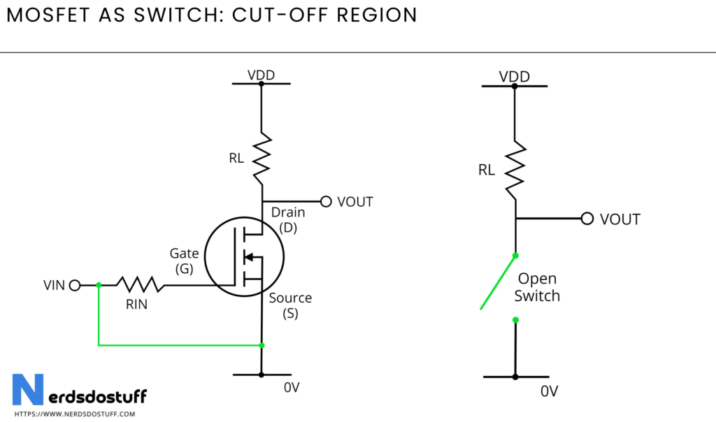
When a MOSFET is operating as a switch in the cut-off region, it means that the transistor is in its “off” state, effectively blocking the flow of current between its source and drain terminals. This state is achieved by applying a voltage to the gate terminal that is below the MOSFET’s threshold voltage.
Working:
- Gate-Source Voltage (VGS) Below Threshold: In the cut-off region, the voltage applied to the gate terminal (VGS) is kept below the MOSFET’s threshold voltage (Vth). The threshold voltage is the minimum voltage required to create a conducting channel between the source and drain terminals.
- Insulating Oxide Layer: When VGS is below the threshold voltage, the insulating oxide layer between the gate and the semiconductor material of the MOSFET remains intact. This oxide layer acts as an insulator, preventing the flow of charge carriers (electrons or holes) between the gate and the semiconductor.
- Absence of Conducting Channel: Since the threshold voltage is not reached, a conducting channel does not form between the source and drain terminals. Without this channel, there is no path for current to flow between the source and drain terminals.
- Depletion Region: Near the drain terminal, a depletion region may exist. This region is depleted of charge carriers, creating a barrier that further prevents the flow of current between the source and drain.
- High Input Impedance: The MOSFET in the cut-off region exhibits a high input impedance, meaning it draws very little current from the input source. This characteristic makes it suitable for applications where low power consumption is important.
Saturation Region

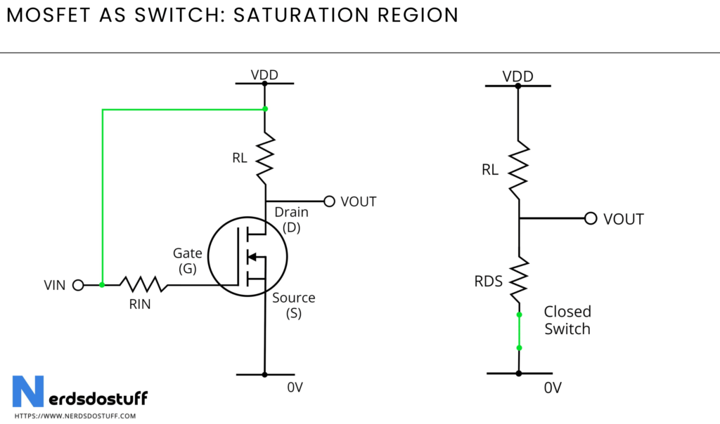
In the saturation region, a MOSFET operates as a switch by allowing a significant current to flow between its source and drain terminals. This region is characterized by the presence of a conducting channel between the source and drain terminals.
Working:
- Gate-Source Voltage (VGS) Applied: To turn the MOSFET on and bring it into the saturation region, a voltage greater than the threshold voltage (Vth) is applied to the gate terminal. This voltage creates an electric field that attracts charge carriers (electrons for an N-channel MOSFET or holes for a P-channel MOSFET) to the surface of the semiconductor material.
- Formation of Conducting Channel: As the gate voltage exceeds the threshold, a conducting channel is formed beneath the oxide layer on the semiconductor surface. This channel provides a low-resistance path for current flow between the source and drain terminals.
- Drain-Source Voltage (VDS) Applied: A voltage known as the drain-source voltage (VDS) is applied across the drain and source terminals. This voltage drives the flow of charge carriers through the conducting channel.
- Saturated State: In the saturation region, the MOSFET is in a saturated state, meaning the channel is fully established, and it allows the maximum current to flow for the given VGS and VDS conditions. The MOSFET is acting as a closed switch with low resistance, facilitating the flow of current between the source and drain.
- Minimized Depletion Region: The depletion region near the drain terminal is minimized in the saturation region, reducing the resistance to the flow of charge carriers. This contributes to the low resistance state of the MOSFET.
- Low Output Impedance: The MOSFET in saturation exhibits low output impedance, meaning it can drive a load with minimal impact on the voltage across the terminals. This characteristic is advantageous in applications where a strong and stable output signal is required.
- Controlled by VGS and VDS: The saturation region is primarily determined by both the gate-source voltage (VGS) and the drain-source voltage (VDS). Proper control of these voltages is essential for maintaining the MOSFET in the saturation region.
Characteristics

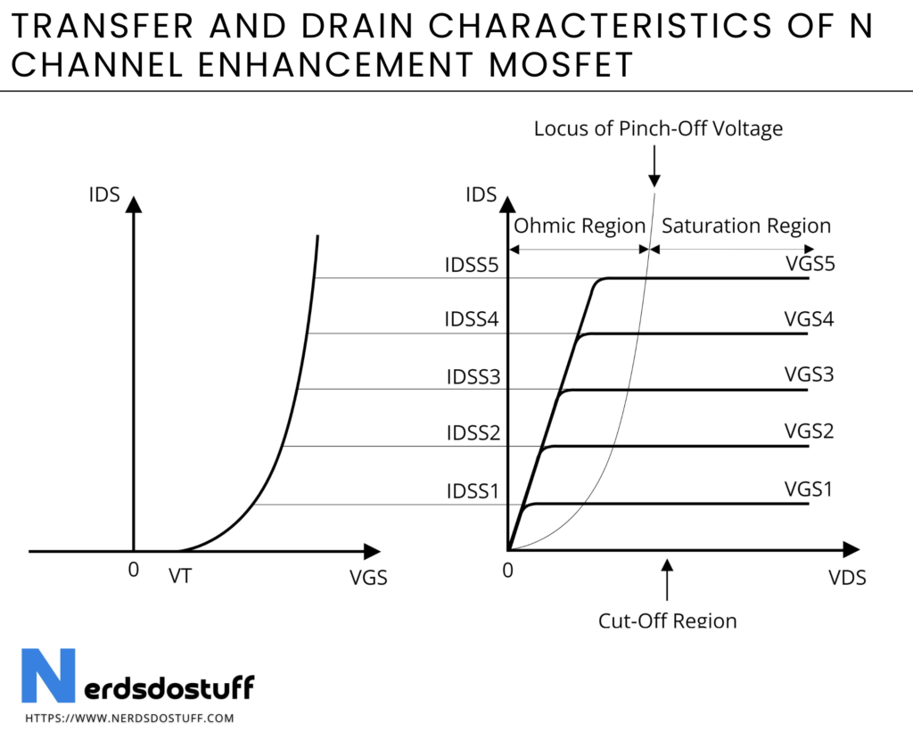
- In an enhancement-mode MOSFET, the threshold voltage (Vth) is positive. The MOSFET is normally off and requires a positive gate-source voltage to turn on, entering the saturation region.
- Transfer characteristics show that the MOSFET remains off (cut-off region) until the gate-source voltage exceeds the threshold voltage.
- Once the gate-source voltage surpasses Vth, the MOSFET enters the saturation region, allowing a significant drain current to flow.
Switching Characteristics
| Sr. No. | MOSFET | VGS<<0 | VGS=0 | VGS>>0 |
|---|---|---|---|---|
| 1 | N Channel Enhancement MOSFET | OFF | OFF | ON |
| 2 | P Channel Enhancement MOSFET | ON | OFF | OFF |
| 3 | N Channel Depletion MOSFET | OFF | ON | ON |
| 4 | P Channel Depletion MOSFET | ON | ON | OFF |
FAQs
Q. How does a MOSFET switch work?
A MOSFET switch operates by applying a voltage to the gate terminal. When the gate-source voltage exceeds the threshold, a conducting channel is formed, allowing current to flow between the source and drain terminals.
Q. What is the significance of threshold voltage in MOSFET switching?
The threshold voltage is crucial in MOSFET switching. Below this voltage, the MOSFET remains in the off state (cut-off region), and above it, the MOSFET enters the on state (saturation region), allowing current flow.
Q. What are the advantages of using MOSFETs as switches?
MOSFETs offer advantages such as high switching speed, low power consumption, small size, and compatibility with integrated circuits. They are widely used in electronic devices for their efficiency in switching applications.
Q. How does the MOSFET switch handle different voltage levels?
MOSFET switches are designed to operate with different voltage levels. The threshold voltage determines when the switch turns on, and the voltage across the source and drain terminals influences the amount of current flowing through the switch.
Q. What are the key parameters to consider when using a MOSFET as a switch?
Important parameters include the threshold voltage, on-state resistance (RDS(on)), maximum drain-source voltage (VDS), and gate-source voltage (VGS) levels. These parameters affect the switch’s performance and compatibility with the application.
Q. How does temperature affect MOSFET switch performance?
Temperature can impact the characteristics of a MOSFET switch. It is crucial to consider the MOSFET’s temperature ratings and thermal properties to ensure reliable performance under varying temperature conditions. Thermal management is often necessary for high-power applications.


