What is Phase Locked Loop (PLL) ?
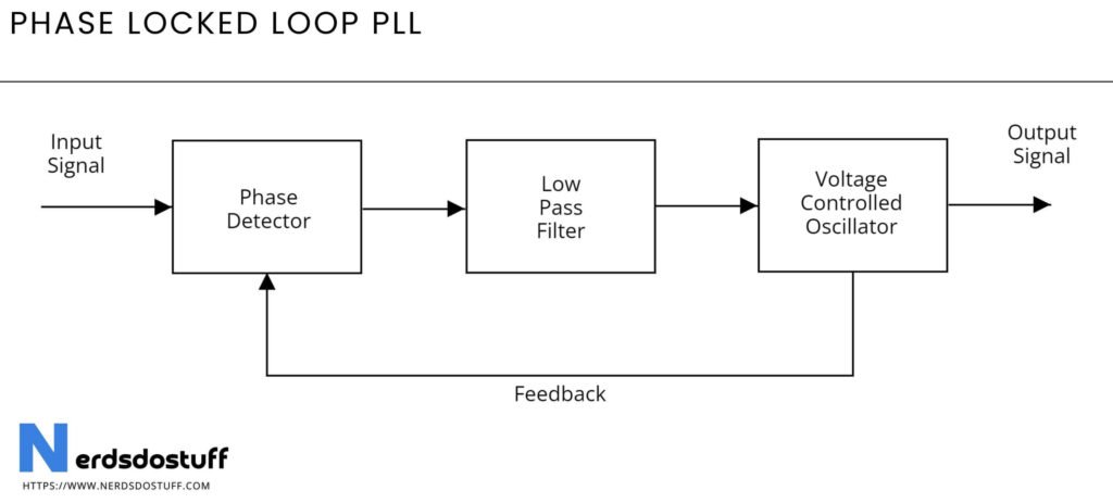
A phase-locked loop (PLL) is an electronic control system that synchronizes an output signal’s phase and frequency with a reference signal’s phase and frequency. It consists of a phase detector, a low-pass filter, a voltage-controlled oscillator (VCO), and often a frequency divider. The phase detector compares the phase of the input reference signal with the phase of the signal from the VCO and generates an error signal that represents the phase difference between the two signals. This error signal is then filtered and used to adjust the frequency of the VCO, effectively aligning the VCO’s output phase and frequency with the reference signal.
The operation of a PLL begins with the phase detector generating an error signal proportional to the phase difference between the reference signal and the VCO output. This error signal is processed by the low-pass filter to remove high-frequency noise and to produce a smooth control voltage. The control voltage is then fed to the VCO, which adjusts its output frequency in response to the control voltage. If the VCO frequency deviates from the reference signal, the phase detector will produce an error signal to correct the VCO, maintaining a locked condition where the VCO output is synchronized with the reference signal.
Phase Locked Loop Diagram

Working of Phase Locked Loop
The operation of a phase-locked loop (PLL) begins with the phase detector, a crucial component that compares the phase of an input reference signal with the phase of a feedback signal generated by the voltage-controlled oscillator (VCO). The phase detector produces an error signal proportional to the phase difference between these two signals. This error signal represents how much the VCO output deviates from the reference signal in terms of phase and frequency. If the phases of the two signals are aligned, the error signal will be minimal or zero.
This error signal is then passed through a low-pass filter, which smooths out high-frequency noise and other rapid variations, producing a clean control voltage. The low-pass filter is essential for ensuring the stability of the PLL by removing unwanted frequency components that could cause the VCO to oscillate erratically. The filtered control voltage directly affects the VCO, which adjusts its output frequency based on the control voltage it receives. The VCO’s frequency increases or decreases to reduce the phase difference, effectively aligning the VCO output with the reference signal.
As the VCO output becomes synchronized with the reference signal, the PLL reaches a “locked” state, where the output frequency is stable and matches the reference frequency. In this locked state, the phase detector continuously monitors the phase difference and makes minor adjustments to the VCO to maintain synchronization. This feedback loop allows the PLL to track the reference signal accurately, even if there are slight variations in the input frequency.
Applications of Phase Locked Loop
- Frequency Synthesis:
- PLLs are widely used in frequency synthesizers to generate a range of frequencies from a single reference frequency. This is crucial in radio, telecommunications, and signal processing, where precise and stable frequencies are needed.
- Clock Generation and Distribution:
- In digital systems, PLLs are employed to generate and distribute clock signals. They can lock onto an external clock and produce a higher-frequency clock used by the internal circuitry of microprocessors, ensuring synchronization across various components.
- Demodulation:
- PLLs are used in communication systems for demodulating frequency-modulated (FM) or phase-modulated (PM) signals. The PLL locks onto the carrier signal and tracks its phase changes to recover the original information signal.
- Motor Speed Control:
- In industrial applications, PLLs are utilized to control the speed of motors. By comparing the phase of the motor’s rotational signal with a reference signal, the PLL can adjust the motor speed to match the desired speed accurately.
- Data Recovery:
- In data communication, PLLs play a critical role in data recovery from noisy environments. They help in synchronizing the timing of data sampling with the received signal, ensuring accurate data extraction.
- Frequency Translation:
- PLLs are used in frequency translation systems, such as mixers in radio receivers, to convert signals from one frequency band to another. This is essential for tuning and selecting specific channels in radio and television receivers.


