What is PLL IC LM565
The LM565 is a versatile Phase Locked Loop (PLL) integrated circuit (IC) designed for various frequency and phase synchronization applications. It contains a voltage-controlled oscillator (VCO), phase detector, and an internal amplifier, all integrated into a single package. The IC operates within a frequency range of 0.001 Hz to 500 kHz, making it suitable for both low and high-frequency applications. It is commonly used in frequency synthesis, modulation and demodulation, frequency multiplication, and tone decoding. The LM565 is known for its high stability, wide operating frequency range, and ease of use, which makes it a popular choice for designing communication systems, signal processing units, and control systems.
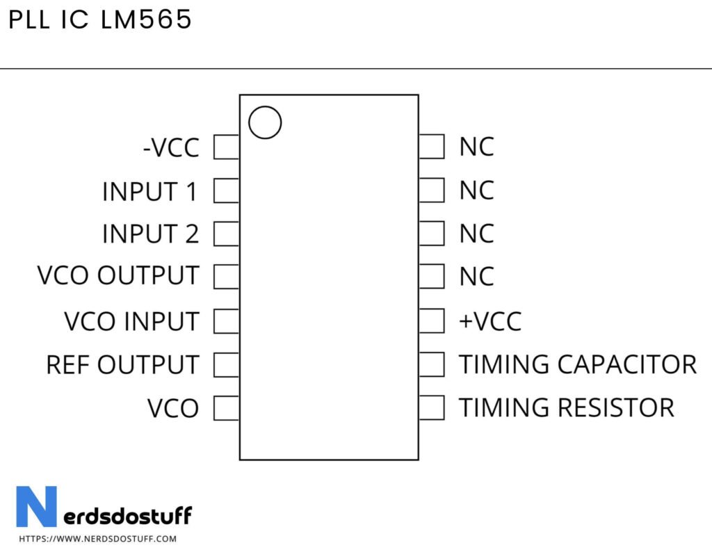
PLL IC LM565 Diagram

LM565 Pin Configuration
- Pin 1 (Ground): Ground connection for the IC.
- Pin 2 (Output of Phase Detector): The output signal of the phase detector, usually connected to a low-pass filter.
- Pin 3 (VCO Input): Input to the voltage-controlled oscillator (VCO).
- Pin 4 (VCO Output): Output of the VCO, providing the generated frequency.
- Pin 5 (Vcc): Positive power supply voltage for the IC.
- Pin 6 (VCO Timing Capacitor): Connection for the external capacitor that sets the VCO frequency.
- Pin 7 (VCO Timing Resistor): Connection for the external resistor that sets the VCO frequency.
- Pin 8 (Frequency Divider Output): Output of the frequency divider, used in frequency synthesis applications.
- Pin 9 (Phase Detector Input): Input to the phase detector.
- Pin 10 (VCO Control Voltage): Input for the control voltage to the VCO.
- Pin 11 (No Connection): Not connected internally, often left unconnected.
- Pin 12 (Frequency Divider Input): Input to the frequency divider.
- Pin 13 (Lock Indicator): Indicates when the PLL is in a locked state.
- Pin 14 (Phase Detector Input): Another input to the phase detector.
Features of LM565
| Feature | Description |
|---|---|
| Package Type | 14-pin Dual Inline Package (DIP) |
| Operating Voltage Range | Typically 10V to 22V |
| Frequency Range | 0.001 Hz to 500 kHz (approximately) |
| Internal Components | Contains a phase detector, voltage-controlled oscillator (VCO), and internal amplifier |
| Frequency Stability | High stability |
| Control Voltage Range | Adjustable control voltage for VCO |
| Applications | Frequency synthesis, modulation/demodulation, frequency multiplication, tone decoding, etc. |
| Output Signals | Output of phase detector, VCO output, frequency divider output |
| External Components | Requires external components such as resistors, capacitors, and filters for setting frequency and gain |
| Lock Indicator | Includes a lock indicator pin to signal when the PLL is in a locked state |
| Power Supply | Requires a positive power supply voltage (Vcc) |
| Ease of Use | Known for ease of implementation and straightforward operation |
Working of PLL IC LM565
The LM565 Phase Locked Loop (PLL) IC operates on the principle of phase and frequency synchronization between an input signal and a voltage-controlled oscillator (VCO). At its core, the LM565 consists of three main components: a phase detector, a VCO, and an internal amplifier.
Firstly, the phase detector compares the phase of the input signal (usually a reference signal) and the output signal from the VCO. It generates an error signal proportional to the phase difference between these two signals. This error signal is then filtered and amplified to control the VCO’s frequency.
Secondly, the voltage-controlled oscillator (VCO) generates an output signal whose frequency is directly proportional to the voltage applied to its control input. The filtered and amplified error signal from the phase detector adjusts this control voltage, thereby controlling the VCO’s output frequency.
Finally, the output signal from the VCO is fed back to the phase detector, closing the feedback loop. As the VCO’s frequency changes in response to the error signal, the phase difference between the input and VCO signals decreases. The phase-locked loop achieves lock when the phase difference between the input and VCO signals becomes zero or very close to zero, indicating synchronization. Once locked, the VCO output frequency is precisely controlled and tracks changes in the input signal.
Applications of PLL IC LM565
- Frequency Synthesis:
- The LM565 is commonly used in frequency synthesizers to generate precise and stable output frequencies from a reference signal. This is essential in radio communication, where different channels or frequencies need to be synthesized from a single reference frequency.
- Modulation and Demodulation:
- In communication systems, the LM565 is utilized for both modulation and demodulation tasks. It can lock onto a carrier signal’s frequency and phase, facilitating the modulation of information onto the carrier signal and the subsequent demodulation of the modulated signal to recover the original information.
- Clock Generation:
- PLLs are extensively used in digital systems for clock generation and synchronization. The LM565 can generate stable clock signals with precise frequencies, ensuring synchronous operation of various digital components in microprocessors, memory systems, and communication interfaces.
- Frequency Multiplication:
- The LM565 can be employed to multiply the frequency of an input signal. By using appropriate feedback and control mechanisms, the PLL can generate an output signal with a frequency that is a multiple of the input frequency. This is useful in applications such as clock multiplication in digital circuits.
- Tone Decoding:
- The LM565 can be used for tone decoding applications, where specific frequency tones need to be detected or decoded. By locking onto the frequency of the input tone, the PLL can provide an output signal or trigger an action when the desired tone is detected, making it useful in tone-based control systems and signal processing.
- Data Synchronization:
- PLLs are employed in data communication systems for synchronization and clock recovery purposes. The LM565 can recover the clock signal from the received data stream, ensuring accurate timing for data sampling and processing. This helps in maintaining synchronization between the transmitter and receiver in digital communication systems.


