What is Voltage to Current Converter ?
A voltage to current converter, also known as a V-I converter or transconductance amplifier, is an electronic device that transforms an input voltage signal into a proportional output current. This type of conversion is crucial in various applications where it is more advantageous to work with current signals rather than voltage signals. One common scenario is in the control of actuators and sensors, where a current signal is less susceptible to noise and voltage drops over long distances compared to a voltage signal. The basic principle involves using an operational amplifier (op-amp) in conjunction with a resistor or a current-setting component to produce a current that is directly proportional to the input voltage.
These converters are widely used in industrial and instrumentation applications. For instance, in the field of analog signal processing, V-I converters are essential for interfacing with devices that require current input, such as certain types of analog meters or LEDs in optical communication systems. They are also used in feedback control systems where maintaining a constant current is critical, such as in power supply circuits and transducer signal conditioning.
Types of Voltage to Current Converter
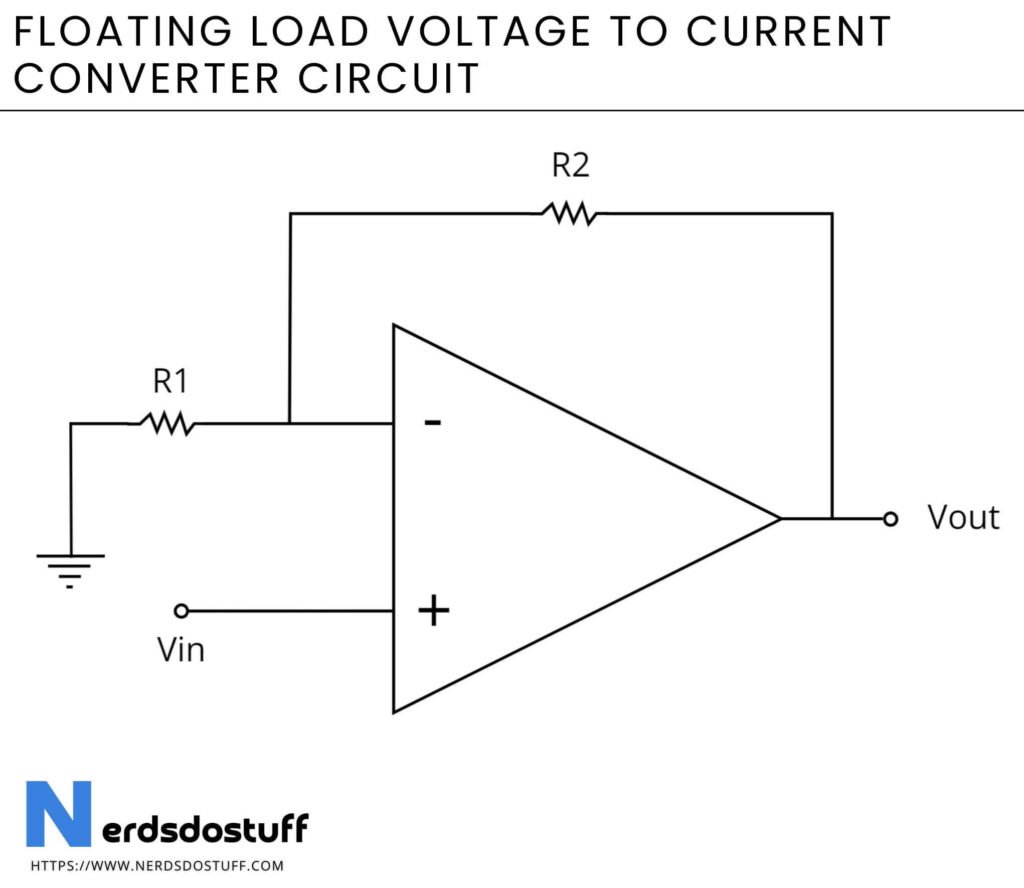
- Floating Load Configuration: In this configuration, the load is connected in series with the output of the operational amplifier. The input voltage is applied to the non-inverting input, while the inverting input is connected through a resistor to the output. The current through the load is proportional to the input voltage and is determined by the value of the feedback resistor.
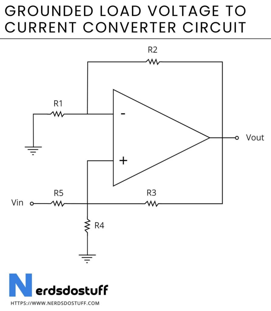
- Grounded Load Configuration: Here, the load is connected to the ground. The operational amplifier drives a transistor or a MOSFET to control the current through the load. This configuration is particularly useful when the load needs to be referenced to the ground.
Floating Load Voltage to Current Converter Circuit

Gounded Load Voltage to Current Converter Circuit

Working of Voltage to Current Converter
The operation of a voltage to current converter primarily involves the use of an operational amplifier (op-amp) and a feedback mechanism to produce a current that is directly proportional to the input voltage. In a typical configuration, the input voltage is applied to the non-inverting input of the op-amp. The inverting input is connected to the output through a feedback resistor, with the load connected in series. The op-amp works to balance its inputs by adjusting its output voltage, thus ensuring that the voltage across the feedback resistor is equal to the input voltage. This results in a current through the feedback resistor, and consequently through the load, that is proportional to the input voltage divided by the resistance of the feedback resistor.
In the case of a grounded load configuration, the op-amp drives a transistor or MOSFET to control the current through the load. The input voltage is applied to the non-inverting input of the op-amp, which controls the gate or base of the transistor. The transistor adjusts the current through the load to match the desired level. The feedback from the load to the inverting input of the op-amp ensures that any deviation in current is corrected by adjusting the transistor’s conductivity. This closed-loop system maintains a stable current that is directly proportional to the input voltage, providing precise control and making the voltage to current converter effective for various applications where stable current output is essential.
Applications of Voltage to Current Converter
- Analog Signal Transmission: In industrial environments, transmitting analog signals over long distances can lead to signal degradation due to noise and voltage drops. V-I converters are used to convert voltage signals to current signals, which are less susceptible to these issues. The current signal is then transmitted and converted back to a voltage signal at the receiving end.
- LED Drivers: LEDs require a constant current for stable operation and to maintain consistent brightness. V-I converters are used in LED driver circuits to ensure a constant current is supplied to the LEDs, irrespective of variations in the input voltage, thereby protecting the LEDs and prolonging their lifespan.
- Temperature Sensors: Many temperature sensors, such as thermocouples and RTDs, produce a voltage output proportional to temperature. A V-I converter can be used to convert this voltage signal into a current signal, which can then be easily transmitted to a monitoring system or used to drive an actuator in a temperature control system.
- 4-20 mA Current Loop Systems: Widely used in industrial process control, 4-20 mA current loops use V-I converters to translate sensor outputs (voltage signals) into current signals. These current signals can be transmitted over long distances with high accuracy and are less affected by electrical noise. The current loop also allows for easy monitoring and fault detection.
- Transducer Signal Conditioning: Transducers convert physical quantities (like pressure, force, or light intensity) into electrical signals, often voltage. V-I converters are used to convert these voltage signals into current signals for more robust transmission and processing, especially in harsh environments.
- Analog-to-Digital Conversion: In some analog-to-digital conversion processes, it is beneficial to first convert the voltage signal to a current signal. This is particularly useful in certain DACs (digital-to-analog converters) where a current output is needed to interface with other components or systems that operate based on current signals rather than voltage signals.


